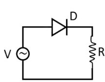
A p-n junction diode (D) shown in figure below can act as a rectifier. An alternating current source (V) is connected in the circuit. The current (I) in the resistor (R) can be shown by which graph?
Answer & explanation
Correct answer: option 2
The correct answer is Option (2)
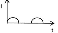
A single diode in series with the load forms a half-wave rectifier. During the half cycle in which the source makes the diode forward biased, current flows through R and follows the shape of the input. During the other half cycle the diode is reverse biased and blocks the current, so the current is zero. The output is therefore a series of half-sine pulses in one direction only, with a gap of one half cycle after each pulse.
Why the other options are incorrect
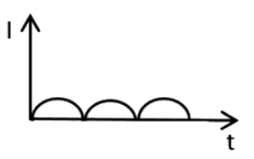
Option (1) — Incorrect. Pulses in every half cycle with no gaps are the output of a full-wave rectifier, which needs two diodes (or a bridge of four).
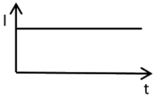
Option (3) — Incorrect. A steady current needs a filter (for example a capacitor) after the rectifier; a diode alone gives a pulsating current.
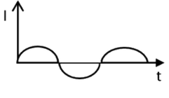
Option (4) — Incorrect. Current in both directions is the unrectified alternating current; the diode blocks the reverse half.
NCERT (2026-27):
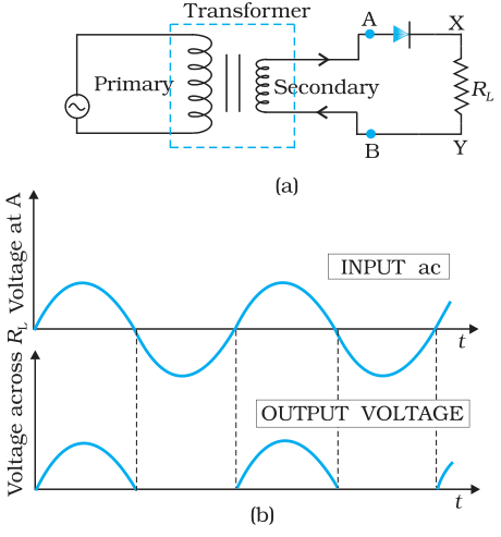
Application of Junction Diode as a Rectifier – “… If an alternating voltage is applied across a diode in series with a load, a pulsating voltage will appear across the load only during the half cycles of the ac input during which the diode is forward biased. Such rectifier circuit, as shown in Fig. 14.18, is called a half-wave rectifier. … Therefore, in the positive half-cycle of ac there is a current through the load resistor \( R_L \) and we get an output voltage, as shown in Fig. 14.18(b), whereas there is no current in the negative half-cycle.”