
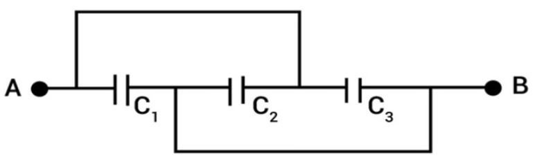
In the figure, the equivalent capacitance between A and B is
Answer & explanation
Correct answer: option 1
The correct answer is Option (1) → \( C_1+C_2+C_3 \)
Points joined by a plain connecting wire are at the same potential and can be treated as one point. Capacitors connected across the same two points have the same potential difference and are in parallel.
From the figure, the connecting wires join these points:
The upper wire joins A to the junction of \( C_2 \) and \( C_3 \), so that junction is the point A.
The lower wire joins the junction of \( C_1 \) and \( C_2 \) to B, so that junction is the point B.
Each capacitor can then be placed between these points:
\( C_1 \) between A and the \( C_1 \)–\( C_2 \) junction, that is, between A and B
\( C_2 \) between the \( C_1 \)–\( C_2 \) junction and the \( C_2 \)–\( C_3 \) junction, that is, between B and A
\( C_3 \) between the \( C_2 \)–\( C_3 \) junction and B, that is, between A and B
All three capacitors have the same potential difference \( V_{AB} \) across them, so they are in parallel and their capacitances add:
\( C_{AB}=C_1+C_2+C_3 \)