
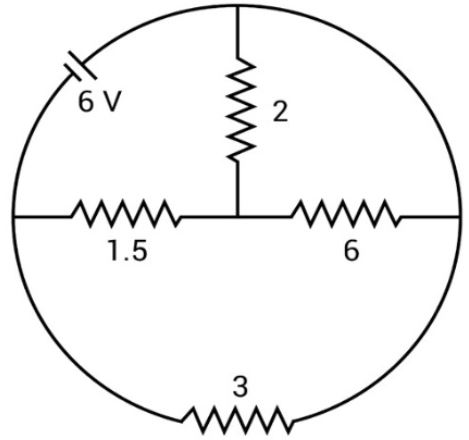
In the circuit shown, the curved arc joining the top junction to the right-hand junction is a plain connecting wire of negligible resistance, the battery is ideal and all resistances are in ohm. The total current supplied by the battery is
Answer & explanation
Correct answer: option 1
The correct answer is Option (1) → 4 A
Points joined by a plain connecting wire are at the same potential and can be treated as one point. Redrawing the circuit this way shows which resistors are in series and which are in parallel.
From the figure, call the left junction L, the centre junction O, the right junction R and the top junction T. The battery lies on the arc from L to T. The arc from T to R is a plain wire, so T and R are the same point. The resistors then sit as follows:
\( 2\,\Omega \) between T and O, that is, between R and O
\( 6\,\Omega \) between O and R
\( 1.5\,\Omega \) between L and O
\( 3\,\Omega \) between L and R (the lower arc)
The \( 2\,\Omega \) and \( 6\,\Omega \) resistors are both between R and O, so they are in parallel:
\( \begin{aligned} R_{\mathrm{RO}} &= \frac{2\times6}{2+6}\,\Omega \\ &= 1.5\,\Omega \end{aligned} \)
This is in series with the \( 1.5\,\Omega \) resistor from O to L:
\( \begin{aligned} R_{\mathrm{ROL}} &= 1.5\,\Omega+1.5\,\Omega \\ &= 3\,\Omega \end{aligned} \)
The \( 3\,\Omega \) path R → O → L is in parallel with the \( 3\,\Omega \) lower arc between L and R:
\( \begin{aligned} R_{\mathrm{eq}} &= \frac{3\times3}{3+3}\,\Omega \\ &= 1.5\,\Omega \end{aligned} \)
The battery is connected across L and R, so the current it supplies is:
\( \begin{aligned} I &= \frac{V}{R_{\mathrm{eq}}} \\ &= \frac{6\,\mathrm{V}}{1.5\,\Omega} \\ &= 4\,\mathrm{A} \end{aligned} \)