
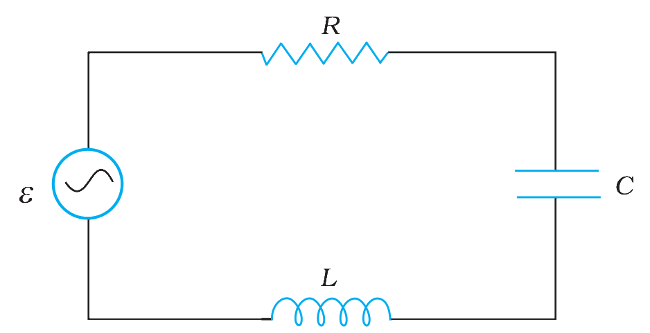
Which of the following correctly describes the circuit shown?
Answer & explanation
Correct answer: option 1
The correct answer is Option (1) → It is an LCR circuit.
Option (1) It is an LCR circuit. — Correct. The loop in the figure has a resistor (the zigzag at the top) and a capacitor (the two parallel plates on the right). It also has an inductor (the coil at the bottom). All three are joined one after another with the ac source. So it is a series LCR circuit.
Option (2) It is an LC circuit. — Incorrect. An LC circuit has no resistor, but the zigzag at the top of the loop is a resistor.
Option (3) It is an LR circuit. — Incorrect. An LR circuit has no capacitor, but the two parallel plates on the right are a capacitor.
Option (4) It is a CR circuit. — Incorrect. A CR circuit has no inductor, but the coil at the bottom of the loop is an inductor.
NCERT (2026-27):
AC Voltage Applied to a Series LCR Circuit – “Figure 7.10 shows a series LCR circuit connected to an ac source ε. As usual, we take the voltage of the source to be v = vm sin ωt.”
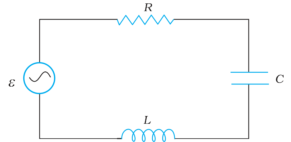
Fig. 7.10: A series LCR circuit connected to an ac source.