
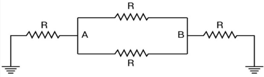
The effective resistance between points A and B in the circuit shown in the figure is (the two ends marked with the earth symbol are connected to each other)
Answer & explanation
Correct answer: option 3
The correct answer is Option (3) → \( 2R/5 \)
Resistors joined end to end, with nothing branching off between them, are in series. Their resistances add. Resistors connected between the same two points are in parallel, and their reciprocals add.
From the figure, with the two earthed ends joined to each other, there are two paths between A and B:
the two resistors \( R \) drawn directly between A and B, which are in parallel with each other;
the outer path from A through the left \( R \), the joined earth wire and the right \( R \) to B, which is two resistors in series.
The two direct resistors in parallel give:
\( \begin{aligned} R_1 &= \frac{R\times R}{R+R} \\ &= \frac{R}{2} \end{aligned} \)
The outer path gives:
\( \begin{aligned} R_2 &= R+R \\ &= 2R \end{aligned} \)
Both paths join A to B, so \( R_1 \) and \( R_2 \) are in parallel:
\( \begin{aligned} R_{AB} &= \frac{R_1R_2}{R_1+R_2} \\ &= \frac{(R/2)\times2R}{R/2+2R} \\ &= \frac{R^{2}}{5R/2} \\ &= \frac{2R}{5} \end{aligned} \)