

CUET Preparation Today
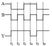
The figure shows the voltage waveforms across two inputs A and B and the output Y of a logic circuit. The logic circuit gate is:
|
OR gate AND gate NOR gate NAND gate |
NAND gate |
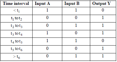
The truth table of the given waveforms is as shown.
As output $Y = \overline{A.B}$ Hence the logic circuit represents NAND gate. |