
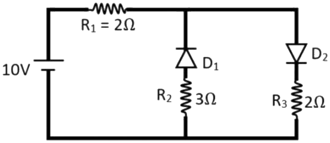
Two ideal diodes are connected as shown in the figure. The current flowing through the resistor \( R_{1} \) is:
Answer & explanation
Correct answer: option 2
The correct answer is Option (2) → \( 2.5\,\mathrm{A} \)
An ideal diode has zero resistance when forward biased and infinite resistance when reverse biased. The longer plate of the cell is its positive terminal, so the top wire is at the higher potential.
Readings from the figure: \( D_1 \) points from the lower wire to the upper wire, so it is reverse biased and its branch (with \( R_2 \)) carries no current. \( D_2 \) points from the upper wire to the lower wire, so it is forward biased and acts as a plain connection. The circuit is then \( R_1 \) in series with \( R_3 \).
\( \displaystyle I = \frac{V}{R_1 + R_3} = \frac{10\,\mathrm{V}}{2\,\Omega + 2\,\Omega} = 2.5\,\mathrm{A} \)