
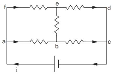
Each resistor shown in figure has a resistance of 20 \( \Omega \) and the battery has an emf of 12 V. The current supplied by the battery is
Answer & explanation
Correct answer: option 2
The correct answer is Option (2) → \( 0.6\,\mathrm{A} \)
The circuit is a balanced bridge. The resistors \( fe \) and \( ab \) are equal, and so are \( ed \) and \( bc \). Points \( f \) and \( a \) are joined by a wire, and so are \( d \) and \( c \). Hence the potential drops along \( fe \) and \( ab \) are equal, and points \( e \) and \( b \) are at the same potential by symmetry.
No current flows through the middle resistor \( eb \), so it can be removed.
\( \displaystyle R_{\mathrm{top}} = 20 + 20 = 40\,\Omega \qquad R_{\mathrm{bottom}} = 20 + 20 = 40\,\Omega \)
The two branches are in parallel across the battery.
\( \displaystyle R_{\mathrm{eq}} = \frac{40 \times 40}{40 + 40} = 20\,\Omega \)
\( \displaystyle I = \frac{\varepsilon}{R_{\mathrm{eq}}} = \frac{12}{20} = 0.6\,\mathrm{A} \)