
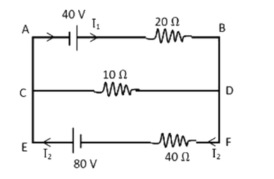
In the circuit as shown in figure, the current through 20 Ω and 40 Ω resistors respectively is:
Answer & explanation
Correct answer: option 2
The correct answer is Option (2) → 2 A in both resistors
All three branches are connected between the same two points (the left side A, C, E and the right side B, D, F), so they have the same potential difference. Apply Kirchhoff’s loop rule to each branch. From the figure, the 40 V cell has its positive terminal towards B and the 80 V cell has its positive terminal towards E, so both drive current round the circuit in the same sense (I1 from A to B, I2 from F to E).
Let \( V = V_{\mathrm{left}} - V_{\mathrm{right}} \).
\( \text{Top branch}: 20 I_1 = 40 + V \)
\( \text{Bottom branch}: 40 I_2 = 80 - V \)
\( \text{Middle branch (left to right)}: 10 I_3 = V \)
Kirchhoff’s junction rule at the left side: the current I2 arriving from the bottom branch leaves through the top and middle branches.
\( \displaystyle I_2 = I_1 + I_3 \)
\( \displaystyle \frac{80 - V}{40} = \frac{40 + V}{20} + \frac{V}{10} \)
\( \displaystyle 80 - V = 80 + 2V + 4V \)
\( \displaystyle V = 0 \)
So no current flows through the 10 Ω resistor, and
\( \displaystyle I_1 = \frac{40\,\mathrm{V}}{20\,\Omega} = 2\,\mathrm{A} \)
\( \displaystyle I_2 = \frac{80\,\mathrm{V}}{40\,\Omega} = 2\,\mathrm{A} \)