
Which of the following diagrams show correctly the biased common emitter n-p-n transistor amplifier circuit?
Answer & explanation
Correct answer: option 1
The correct answer is Option (1)
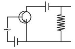
Two things decide the diagram. In the symbol of an n-p-n transistor the arrow on the emitter points away from the base. In a common emitter amplifier the base-emitter junction must be forward biased, so the base side of the input battery must be connected to the positive terminal (the longer plate of the battery symbol), and the emitter side to the negative terminal (the shorter plate).
In Option (1) the emitter arrow points outward, which is the n-p-n symbol, and the long plate of the battery is on the side joined to the base, so the junction is forward biased.
Why the other options are incorrect
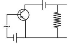
Option (2) — Incorrect. The emitter arrow points towards the base, which is the symbol of a p-n-p transistor.
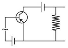
Option (3) — Incorrect. The emitter arrow again points towards the base, so this is a p-n-p transistor.
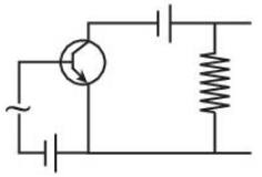
Option (4) — Incorrect. The symbol is n-p-n, but the battery is connected the other way round: its long (positive) plate is on the emitter side, so the base-emitter junction is reverse biased.
Note: This question is from the pre-rationalised NCERT book (2022-23). The topic was removed from the latest NCERT book (2026-27), and it also appears to be out of the CUET 2026 syllabus.
NCERT (Pre-rationalised edition, 2022-23):
Transistor: Structure and Action – “… The transistor works as an amplifier, with its emitter-base junction forward biased and the base-collector junction reverse biased.”
Transistor: Structure and Action – “… Thus in a p-n-p transistor the current enters from emitter into base whereas in a n-p-n transistor it enters from the base into the emitter. The arrowhead in the emitter shows the direction of the conventional current.”