
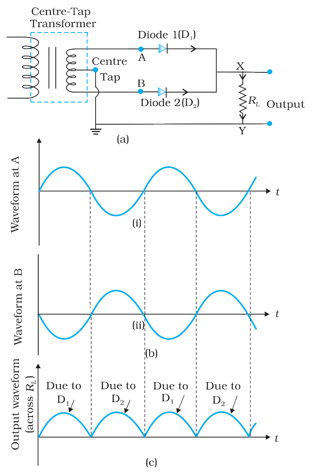
The figure shows a full-wave rectifier circuit, the input waveforms at A and B, and the output across the load \(R_L\).
If diode D2 burns out and stops conducting, the output across \(R_L\) will have
Answer & explanation
Correct answer: option 3
The correct answer is Option (3) → pulses only in the half-cycles in which A is positive, with gaps between them
Each diode conducts only when its own end of the secondary is positive with respect to the centre tap. In the figure, D1 is joined to A and D2 is joined to B.
Option (1) no pulses at all — Incorrect. D1 still works. It conducts whenever A is positive, so current still flows through the load in those half-cycles.
Option (2) pulses in every half-cycle, as before — Incorrect. The pulses marked “Due to D2” in (c) come from D2. With D2 out of action, these pulses are lost.
Option (3) pulses only in the half-cycles in which A is positive, with gaps between them — Correct. Only D1 conducts now. It gives the pulses marked “Due to D1”, which come while the waveform at A is positive. The output becomes a half-wave output.
Option (4) pulses only in the half-cycles in which B is positive, with gaps between them — Incorrect. When B is positive, A is negative and D1 is reverse biased. With D2 not conducting, no current flows in these half-cycles.
NCERT (2026-27):
Application of Junction Diode as a Rectifier – “… Suppose the input voltage to A with respect to the centre tap at any instant is positive. It is clear that, at that instant, voltage at B being out of phase will be negative as shown in Fig.14.19(b). So, diode D1 gets forward biased and conducts (while D2 being reverse biased is not conducting). …”
FIGURE 14.19 (a) A Full-wave rectifier circuit; (b) Input wave forms given to the diode D1 at A and to the diode D2 at B; (c) Output waveform across the load RL connected in the full-wave rectifier circuit.