
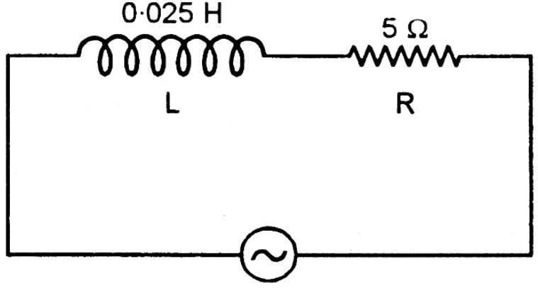
For the LR circuit shown in the figure, the phase angle between the voltage and the current, if the frequency of the source is \( 100/\pi\,\mathrm{Hz} \), is
Answer & explanation
Correct answer: option 3
The correct answer is Option (3) → \( 45^\circ \)
In a series LR circuit the current lags behind the applied voltage by a phase angle \( \phi \). From the impedance diagram (the series LCR circuit with no capacitor), \( \tan\phi=X_L/R \), where \( X_L=\omega L \) is the inductive reactance.
From the figure, \( L=0.025\,\mathrm{H} \) and \( R=5\,\Omega \).
The angular frequency of the source is:
\( \begin{aligned} \omega &= 2\pi\nu \\ &= 2\pi\times\frac{100}{\pi}\,\mathrm{Hz} \\ &= 200\,\mathrm{rad\,s^{-1}} \end{aligned} \)
The inductive reactance is:
\( \begin{aligned} X_L &= \omega L \\ &= 200\,\mathrm{rad\,s^{-1}}\times0.025\,\mathrm{H} \\ &= 5\,\Omega \end{aligned} \)
The phase angle then follows from:
\( \begin{aligned} \tan\phi &= \frac{X_L}{R} \\ &= \frac{5\,\Omega}{5\,\Omega} \\ &= 1 \end{aligned} \)
\( \Rightarrow\; \phi=45^\circ \)