
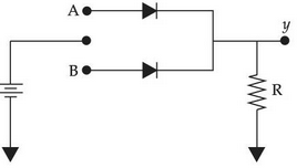
The logic gate realised using p-n junction diodes in the given figure is:
Answer & explanation
Correct answer: option 1
The correct answer is Option (1) → OR gate
| A | B | Output |
| 1 | 0 | 1 |
| 0 | 1 | 1 |
| 1 | 1 | 1 |
| 0 | 0 | 0 |
When either A and B signal is high, the output will be equivalent to OR gate.