
In a series LCR circuit, the capacitive reactance is greater than the inductive reactance. When graphs of the source voltage \(v\) and the current \(i\) are drawn against \(\omega t\), the current
Answer & explanation
Correct answer: option 2
The correct answer is Option (2) → reaches its peak before the voltage
In a series LCR circuit the current is \( i=i_m\sin(\omega t+\phi) \), with \( \tan\phi=(X_C-X_L)/R \). Here \( X_C\gt X_L \), so \( \phi \) is positive and the current is ahead of the voltage.
Option (1) reaches its peak at the same instant as the voltage — Incorrect. The two peak together only when \( \phi=0 \). This happens at resonance, when \( X_C=X_L \).
Option (2) reaches its peak before the voltage — Correct. With \( \phi \) positive, the circuit is mainly capacitive and the current leads the voltage. On the graph the current peak comes earlier than the voltage peak by \( \phi \) on the \( \omega t \) axis.
Option (3) reaches its peak after the voltage — Incorrect. The current peaks after the voltage when \( X_L\gt X_C \). The circuit is then mainly inductive.
Option (4) varies at twice the frequency of the voltage — Incorrect. The source drives the current, so the current has the same angular frequency \( \omega \). Only its phase is different.
NCERT (2026-27):
Phasor-diagram solution – “If XC > XL, φ is positive and the circuit is predominantly capacitive. Consequently, the current in the circuit leads the source voltage. …”
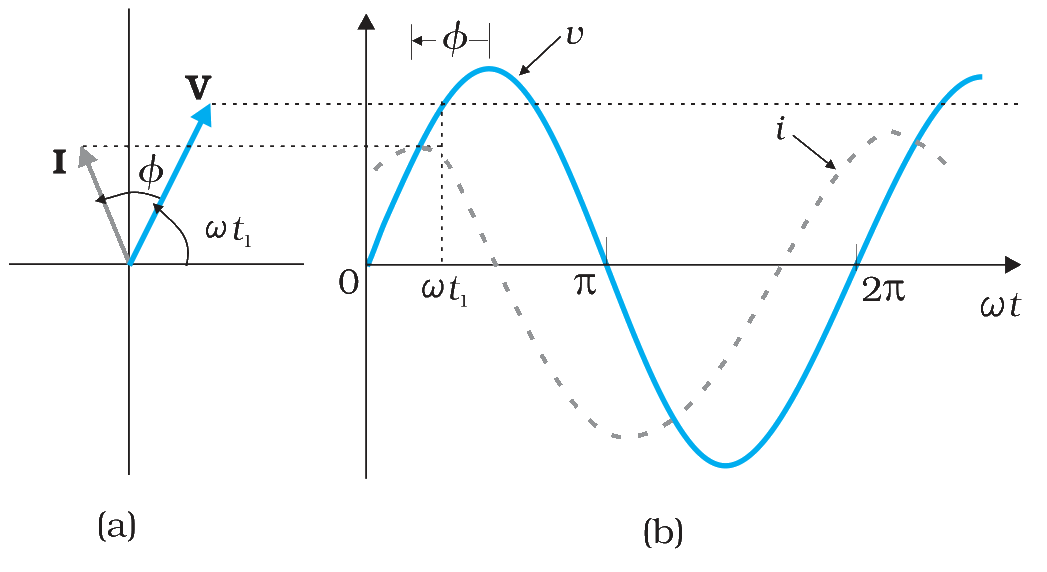
FIGURE 7.13 (a) Phasor diagram of V and I. (b) Graphs of v and i versus ωt for a series LCR circuit where XC > XL.