
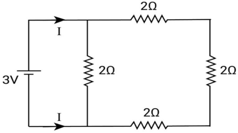
What is the current I in the circuit shown in the figure?
Answer & explanation
Correct answer: option 1
The correct answer is Option (1) → 2 A
Resistors that offer a single path to the current are in series, and resistors connected between the same two points are in parallel. The battery is taken as ideal (no internal resistance).
From the figure, the \( 2\,\Omega \) resistors on the top, right and bottom sides form one path, so they are in series. This branch and the middle \( 2\,\Omega \) resistor join the same two junctions next to the battery. So they are in parallel across the \( 3\,\mathrm{V} \) battery.
The resistance of the series branch is:
\( \begin{aligned} R_{\mathrm{s}} &= R_1+R_2+R_3 \\ &= (2+2+2)\,\Omega \\ &= 6\,\Omega \end{aligned} \)
The series branch in parallel with the middle resistor gives:
\( \begin{aligned} R_{\mathrm{eq}} &= \frac{R_{\mathrm{s}}\,R}{R_{\mathrm{s}}+R} \\ &= \frac{6\,\Omega\times2\,\Omega}{6\,\Omega+2\,\Omega} \\ &= 1.5\,\Omega \end{aligned} \)
The current drawn from the battery is:
\( \begin{aligned} I &= \frac{V}{R_{\mathrm{eq}}} \\ &= \frac{3\,\mathrm{V}}{1.5\,\Omega} \\ &= 2\,\mathrm{A} \end{aligned} \)