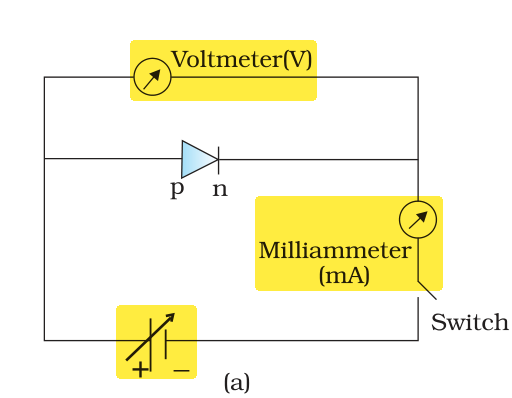
Choose the correct experimental circuit arrangement for studying V-I characteristics a p-n junction diode in forward bias:
Answer & explanation
Correct answer: option 3
The correct answer is Option (3)

A V-I characteristic is a graph of the current through the diode against the voltage across it, so the circuit must do three things:
\( \text{a voltmeter connected in parallel with the diode} \)
\( \text{a milliammeter connected in series with the diode} \)
\( \text{a source whose voltage can be varied} \)
The voltmeter reads the voltage across the diode only, the milliammeter in series carries the same current as the diode, and the variable source (the battery drawn with an arrow) lets the voltage be raised step by step to take a set of readings. Option (3) has all three.
Why the other options are incorrect
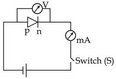
Option (1) — Incorrect. The meters are placed correctly, but the source is a fixed cell, so the voltage across the diode cannot be varied and only one reading can be taken, not a characteristic curve.
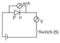
Option (2) — Incorrect. The meters are interchanged: the milliammeter is across the diode, where it would short it, and the voltmeter is in series, where its high resistance blocks the current.

Option (4) — Incorrect. The voltmeter is in series with the diode; it does not measure the diode voltage, and its high resistance stops the current in the circuit.
NCERT (2026-27):
p-n Junction Diode Under Reverse Bias – “… The circuit arrangement for studying the V-I characteristics of a diode, (i.e., the variation of current as a function of applied voltage) are shown in Fig. 14.16(a) and (b). The battery is connected to the diode through a potentiometer (or reheostat) so that the applied voltage to the diode can be changed. … Note that in forward bias measurement, we use a milliammeter since the expected current is large (as explained in the earlier section) while a micrometer is used in reverse bias to measure the current.”