
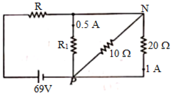
In the circuit shown in the figure, which of the following is correct?
Answer & explanation
Correct answer: option 2
The correct answer is Option (2) → The value of \( R_1=40\,\Omega \)
Points joined by a plain connecting wire are at the same potential. Resistors connected between the same two points are in parallel and have the same potential difference across them.
From the figure, the top end of \( R_1 \) is joined to N by a wire. The lower end of the \( 20\,\Omega \) resistor is joined to P by the bottom wire. So \( R_1 \), the \( 10\,\Omega \) and the \( 20\,\Omega \) resistors all lie between N and P. R is in series with this group across the 69 V cell (internal resistance neglected). The \( 20\,\Omega \) resistor carries 1 A and \( R_1 \) carries 0.5 A.
The potential difference between N and P is:
\( \begin{aligned} V_{NP} &= I_{20}\times20\,\Omega \\ &= 1\,\mathrm{A}\times20\,\Omega \\ &= 20\,\mathrm{V} \end{aligned} \)
The resistance \( R_1 \) is:
\( \begin{aligned} R_1 &= \frac{V_{NP}}{I_1} \\ &= \frac{20\,\mathrm{V}}{0.5\,\mathrm{A}} \\ &= 40\,\Omega \end{aligned} \)
The current in the \( 10\,\Omega \) resistor and the total current through R are:
\( \begin{aligned} I_{10} &= \frac{20\,\mathrm{V}}{10\,\Omega} \\ &= 2\,\mathrm{A} \end{aligned} \)
\( \begin{aligned} I &= 0.5\,\mathrm{A}+2\,\mathrm{A}+1\,\mathrm{A} \\ &= 3.5\,\mathrm{A} \end{aligned} \)
The potential difference across R and its value are:
\( \begin{aligned} V_R &= 69\,\mathrm{V}-20\,\mathrm{V} \\ &= 49\,\mathrm{V} \end{aligned} \)
\( \begin{aligned} R &= \frac{V_R}{I} \\ &= \frac{49\,\mathrm{V}}{3.5\,\mathrm{A}} \\ &= 14\,\Omega \end{aligned} \)
From the above, \( R_1=40\,\Omega \). The current in NP is 2 A, \( R \) is \( 14\,\Omega \) and the potential difference across \( R \) is 49 V. Hence, only the value of \( R_1 \) is correct.