
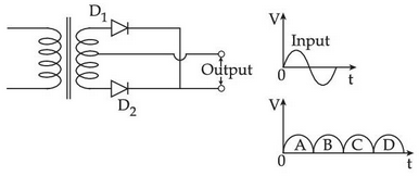
A full wave rectifier circuit along with the output is shown in the figure. The contribution from diode \( D_1 \) are:
Answer & explanation
Correct answer: option 4
The correct answer is Option (4) → A and C only
In a centre-tapped full-wave rectifier each diode conducts in alternate half-cycles of the input: one diode when its end of the secondary is positive, the other when the opposite end is positive.
In the first (positive) half-cycle of the input the upper end of the secondary is positive, so \( D_1 \) is forward biased and conducts, while \( D_2 \) is reverse biased. This half-cycle gives output pulse A.
In the next (negative) half-cycle the lower end is positive, so \( D_2 \) conducts and \( D_1 \) is reverse biased. This gives pulse B.
The pattern repeats, so \( D_1 \) gives the pulses of the positive half-cycles, A and C, and \( D_2 \) gives B and D.
NCERT (2026-27):
Application of Junction Diode as a Rectifier – “… So, diode D1 gets forward biased and conducts (while D2 being reverse biased is not conducting). Hence, during this positive half cycle we get an output current (and a output voltage across the load resistor RL) as shown in Fig.14.19(c). … In this part of the cycle diode D1 would not conduct but diode D2 would, giving an output current and output voltage (across RL) during the negative half cycle of the input ac.”