

CUET Preparation Today
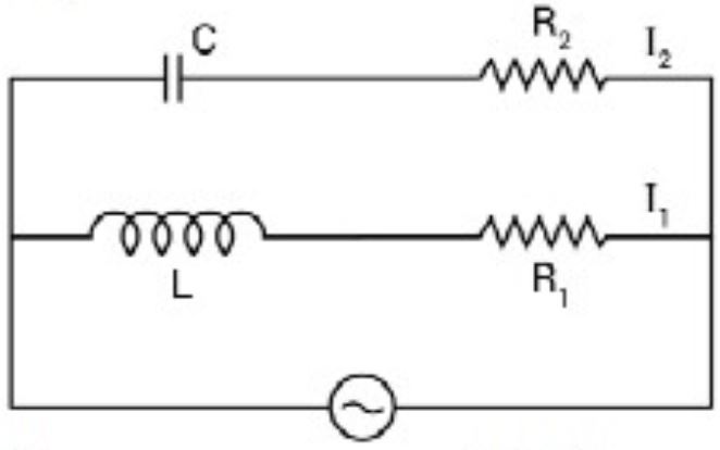
In the above circuit figure $C=\frac{\sqrt{3}}{2}μF, R_2 =50Ω, L=\frac{\sqrt{3}}{10}H$, and $R_1 = 10Ω$. Current in $L-R_1$, path is $I_1$, and in $C-R_2$, path it is $I_2$. The voltage of A. C source is given by, $V=200\sqrt{2}\sin (100t)$ volts. The phase difference between $I_1$ and $I_2$ is
|
60° 150° 90° either (2) or (3) |
150° |
In series RC circuit, the current leads the voltage by an angle in between 0 and 90°. In series RL circuit, the current lags the voltage by an angle in between 0 and 90°. $ \text{phase angle in case 1 is } tan \phi_1 = \frac{X_C}{R} = \frac{1}{\omega CR} = \frac{1000}{\sqrt 3} , \Rightarrow \phi_1 = 90°$ $ \text{phase angle in case 1 is } tan \phi_2 = \frac{X_L}{R} = \frac{\omega L}{R} = \sqrt 3 , \Rightarrow \phi_2 = 60°$ $\text{phase difference } = 90° + 60° =150°$ |