

CUET Preparation Today
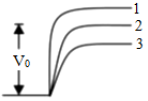
The figure, $V_0$ is the barrier potential across a p – n junction, when no battery is connected across the junction.
|
1 and 3 both correspond to forward bias of junction 1 corresponds to reverse bias of junction and 3 corresponds to forward bias of junction 1 corresponds to forward bias and 3 corresponds to reverse bias of junction 1 and 3 both correspond to reverse bias of junction |
1 corresponds to reverse bias of junction and 3 corresponds to forward bias of junction |
When p – n junction is forward biased, applied voltage opposes the barrier potential resulting decrease in barrier potential. When p – n junction is reverse biased, applied voltage supports the barrier potential resulting increase in barrier potential. Thus, curve 1 corresponds to reverse bias and curve 3 corresponds to forward bias. |