
The experimental circuit arrangements for studying V-I characteristics of a p-n junction diode are given below:
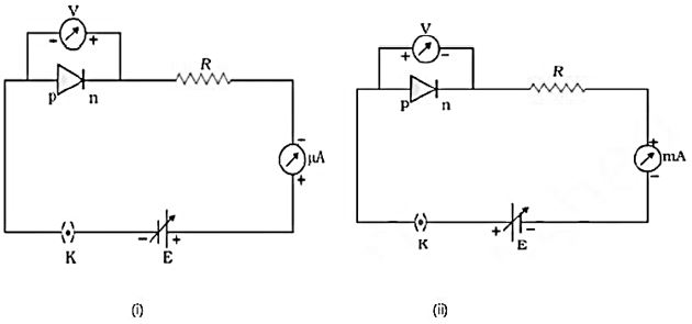
Identify the circuit for forward bias and for reverse bias.
Answer & explanation
Correct answer: option 2
The correct answer is Option (2) → Circuit (i) reverse bias circuit (ii) forward bias
Explanation:
- In circuit (i), the p-side is connected to negative terminal of the battery and n-side is connected to positive terminal. This is reverse biasing. The current is measured in microamperes (μA), which indicates small leakage current typical of reverse bias.
- In circuit (ii), the p-side is connected to positive terminal and n-side to negative terminal. This is forward biasing. The current is measured in milliamperes (mA), indicating a significant current, as expected in forward bias.