CUET Preparation Today
CUET
Physics
Semiconductors and Electronic Devices
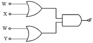
The diagram of a logic circuit is given below. The output F of the circuit is represented by
W . (X + Y)
W . (X . Y)
W + (X . Y)
W + (X + Y)
(W + X) . (W + Y) = W + (X . Y)